Schematic Soil Moisture Sensor Arduino Circuit Diagram

Simple Soil Moisture Detector Circuit Circuit Diagram Circuit Electronics Circuit

Arduino Soil Moisture Sensor And Code Arduino Projects Arduino Simple Arduino Projects

Arduino Based Irrigation And Automatic Plant Watering System Using Soil Moisture Sensor Build Automatic Wate Plant Watering System Aquaponics System Aquaponics

Pin On Arduino Project

Soil Moisture Sensor With Arduino Schematic Diagram Random Nerd Tutorials Arduino Sensor Moisturizer

Green House Monitoring Using Arduino Soil Moisture Sensor Circuit Diagram Arduino Humidity Sensor Circuit Diagram
When soil is moist the current will start flowing from one terminal to another working as a closed circuit.
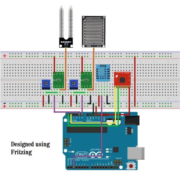
Schematic soil moisture sensor arduino circuit diagram.

Iot Based Smart Irrigation System Using Soil Moisture Sensor And Esp8266 Nodemcu Iot Projects Irrigation System Arduino Projects

A Very Simple Mud Or Soil Moisture Tester Circuit Can Be Built By Using A Single Opamp And A Few Passive C Circuit Projects Electronic Circuit Projects Circuit

Arduino Controlling Relay Moisture Sensor Fritzing Project Soil Moisture Sensor Test Arduino Sensor Moisturizer

Auto Irrigation System Using Soil Moisture Sensor And Pic Microcontroller Irrigation System Irrigation Pic Microcontroller

Soil Moisture Sensor With Arduino Tutorial45 Arduino Arduino Projects Electronics Projects For Beginners

Arduino Irrigation And Automatic Plant Watering With Soil Moisture Sensor Manufacturingstories Arduino Arduino Sensors Arduino Projects

Arduino Based Automatic Plant Irrigation System With Message Alert Arduino Arduino Projects Arduino Laser

Arduino Soil Moisture Sensor Relay Control Arduino Arduino Radio Sensor

Pin On Electronics

Pin On Arduino

Build Your Own Diy Automatic Irrigation System Using Arduino Soil Moisture Sensor And A Solenoid Valve Automatic Irrigation System Arduino Radio Irrigation

Smart Irrigation System Circuit Diagram And Code Irrigation System Circuit Diagram Electronic Schematics

Soil Moisture Detector Circuit Diagram Electronics Circuit Detector Circuit Diagram

Watering System Introduction Arduino Projects Water Systems Arduino

Temphummoistureiotv2 Iot Sensor Humidity Sensor

Dht11 Humidity And Temperature Sensor On Arduino With Lcd Arduino Lcd Arduino Circuit Arduino

A Cheap Soil Moisture Sensor Gardenbot Irrigazione

Arduino Whistle Detector Switch Using Sound Sensor Arduino Arduino Projects Sensor
3

Arduino Distance Detector With A Buzzer And Led S Arduino Arduino Projects Buzzer Arduino

Pin On Sensing And Sensors And Some Actuation

A Panosundaki Pin

Arduino Soil Moisture Sensor With Images Arduino Sensor Moisturizer
Diy Arduino Weather Station Aws Weather Station Arduino Arduino Projects
Source : pinterest.com
